Prairie River Bridge | Internal Braces
Jan 21, 2023
Introduction
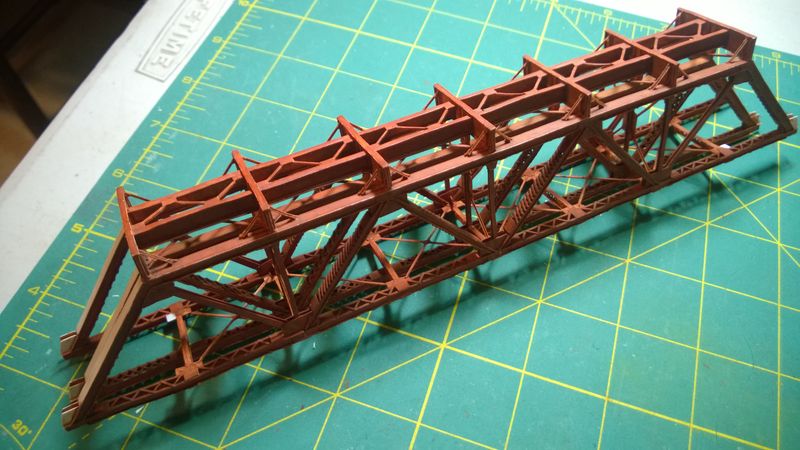
In the previous Prairie River Bridge project article, I had finished attaching the three trusses to the floor beams and installing the floor beam braces. Now that the trusses are attached, I will be adding the internal bracing which includes the lateral struts, sway braces, and lateral cross braces.
Lateral Struts
History
Lateral struts keep the bottoms of the trusses parallel to each other. Similar to the laced steel girders on the trusses, the builders of the Prairie River Bridge used 12" x 18" laced steel "I" beams rivetted together from steel strips, plates, and "L" girders. Steel was expensive and labor was cheap in the 1890s.
When the bridge was constructed in 1899, the lateral struts connected the outer truss directly to each other. When the bridge was strengthened in 1929, every other lateral strut was cut in half and connected to the new center truss with a connector plate, creating the short lateral struts. The remaining long lateral struts did not need to be modified.
Short Struts
Six of the short lateral struts are laid out with two strips of 0.030" x 0.010" styrene strip from Evergreen Scale Models and two plates cut from 0.010" styrene scrap. The plates are attached to the strips as shown in Figure 1. A single layer of lacing cut from 0.020" x 0.010" styrene strip is added on the same side as the plates.
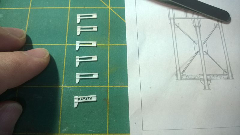
A second set of 0.030" x 0.010" styrene strips is attached to the backs of the short lateral struts. Flanges cut from 0.020" x 0.010" styrene strip are attached to the edge of the existing strips to fabricate four "L" girders as show in in Figure 2. A short piece of 0.020" x 0.010" styrene strip is added to each side of the connector plate under the lower "L" girders.
Long Struts
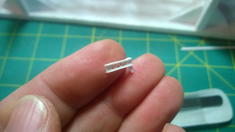
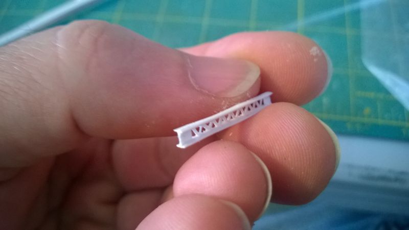
Four of the long lateral struts are laid out with two strips of 0.030" x 0.010" styrene strip and two plates cut from 0.010" styrene scrap. The plates are attached to the strips as shown in Figure 3. A single layer of lacing cut from 0.020" x 0.010" styrene strip is added on the same side as the plates.
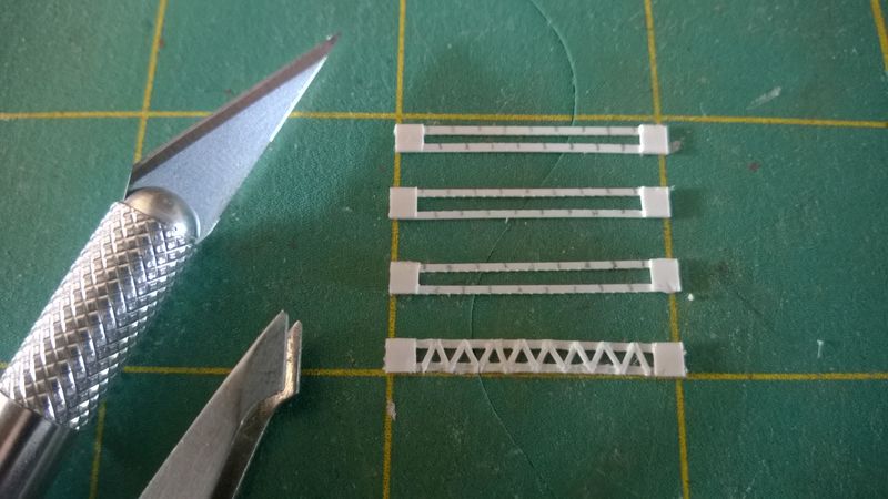
A second set of 0.030" x 0.010" styrene strips is attached to the backs of the long lateral struts. Flanges cut from 0.020" x 0.010" styrene strip are attached to the edge of the existing strips to fabricate four "L" girders as show in in Figure 4. Additional lateral struts will be created when the steel towers on each the end of the main span are installed.
Installation
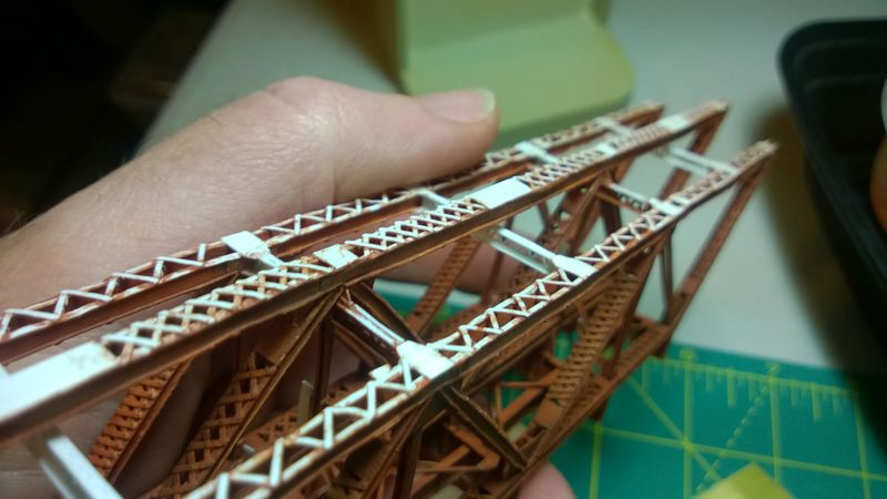
Lateral struts are installed between the bottom of the trusses as shown in Figure 5. Ends of the lateral struts are attached to the connector plates on the outer trusses. Long lateral struts are weaved between the panels on the center truss and connector plates on the short lateral struts are attached to each side of the verticals on the center truss.
Sway Braces
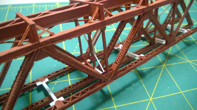
Sway braces are fabricated from 0.020" and 0.030" strips of 0.010" styrene. They are cut to length and installed between the connector plates on the corners of the verticals in the outer trusses and the connector plates in the middle of the verticals on the center truss as shown in Figure 6. The sway bracing was also cut in half when they added the center truss. The original braces would have gone all the way across with small connector plates where they crossed.
Lateral Cross Braces
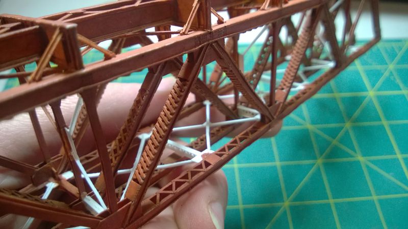
Connector plates for the lateral cross braces are cut from 0.010" styrene scrap and attached to the top corners of the lateral struts where they connect to the outer trusses. Lateral cross braces are fabricated from 0.020" and 0.030" strips of 0.010" styrene and cut to length. After making sure that everything is square, the braces are attached to the connector plates as shown in Figure 7. Additional small connector plates are cut from 0.010" scrap and attached to the braces where they cross. At this point, the entire structure should become very rigid.
Conclusion
I added Archer Fine Transfers N Scale Resin Rivet decals to the backs of the connector plates where the braces attached and then gave everything several thin layers of DecoArt Americana Burnt Sienna acrylic flat base coat as shown in Figure 8. The last connector plates on the ends are left unpainted until the last lateral cross braces are added later. The next step will be to add the rest of the details on the ends of the bridge, starting with the steel towers. After that, it will be time to get started on the deck.
